これまでで、ESP-WROOM-32のプログラムをEclipseで開発することが可能であることがわかりました。
今回は、Eclipseのプロジェクトを(インポートではなく)新規作成してLチカしてみたいと思います。
プログラムそのものは、ESP-IDFが提供しているblinkです。あしからず。
プロジェクト作成
それでは、Eclipseを起動して、プロジェクトを作成していきましょう。
-
Eclipseを起動します。
-
[ファイル]-[新規]-[プロジェクト]を選択します。

-
[Cプロジェクト]を選択します。
-
[次へ]ボタンを押します。
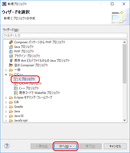
-
[プロジェクト名]を入力します。
-
必要に応じて、[ロケーション]を入力(または参照して選択)します。
-
[プラットフォームでサポートされている場合のみ、プロダクト・タイプとツールチェーンを表示]のチェックを外します。
-
[Makefileプロジェクト]-[空のプロジェクト]を選択します。
-
[Cygwin GCC]を選択します。
-
[次へ]ボタンを押します。
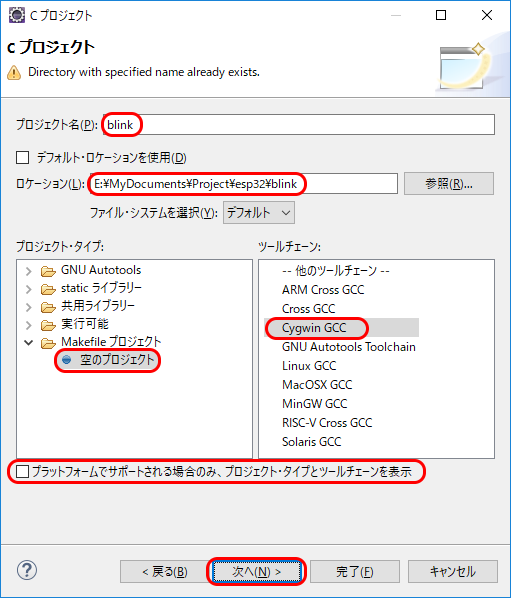
-
[完了]ボタンを押します。
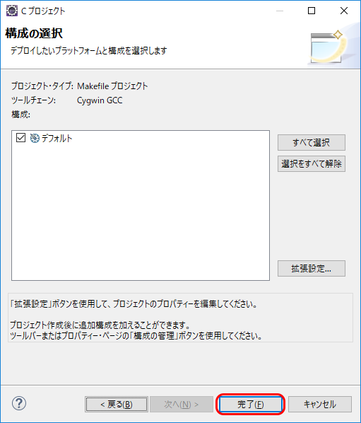
-
プロジェクトを選択してマウスの右ボタンをクリックします。
-
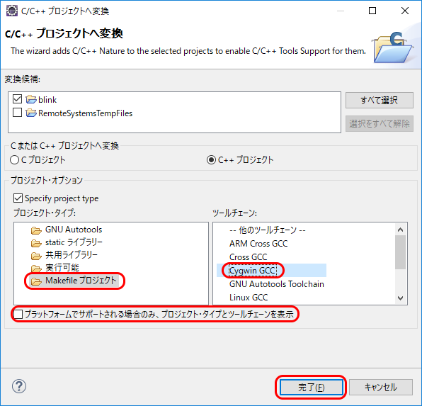
[新規]-[C/C++ プロジェクトへ変換(C/C++ ネーチャー追加)]を選択します。
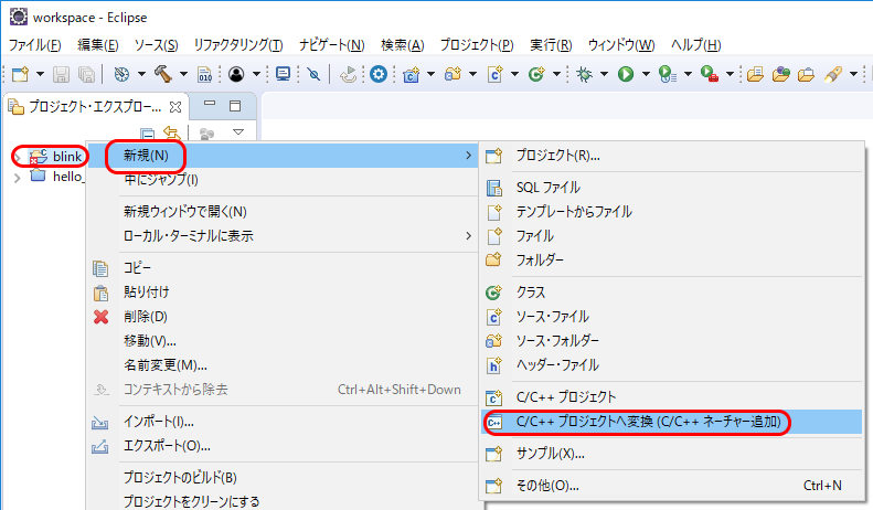
-
[プラットフォームでサポートされている場合のみ、プロダクト・タイプとツールチェーンを表示]のチェックを外します。
-
[Makefile プロジェクト]を選択します。
-
[Cygwin GCC]を選択します。
-
[完了]ボタンを押します。
-
以前(開発環境を作る (2))説明したように、Eclipseのプロジェクト毎の設定をします。
プログラムをコーディング
続いて、プログラムをコーディングしていきたいと思います。
GitHubには、プロジェクトのテンプレートが公開されてますので、こちらをダウンロードしてきても良いのですが、今回はサンプルを参考にして作っていきます。
-
プロジェクトのルートフォルダに
Makefileファイルを作成します。
-
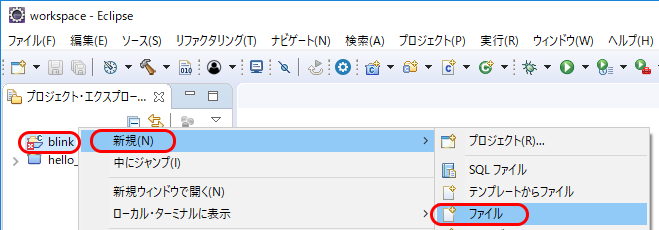
プロジェクト ルート を右クリックして[新規]-[ファイル]を選択します。
-
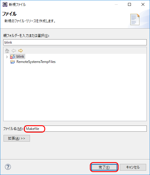
[ファイル名]に
Makefileを入力します。
-
[完了]ボタンを押します。
-
エディタで、次の内容を入力します。
#
# This is a project Makefile. It is assumed the directory this Makefile resides in is a
# project subdirectory.
#

PROJECT_NAME := blink

include $(IDF_PATH)/make/project.mk
-
プロジェクト ルート を右クリックして[新規]-[ファイル]を選択します。
-
プロジェクトのルートフォルダに
mainフォルダを作成します。
-
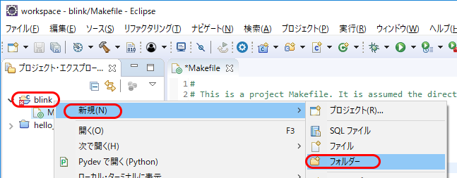
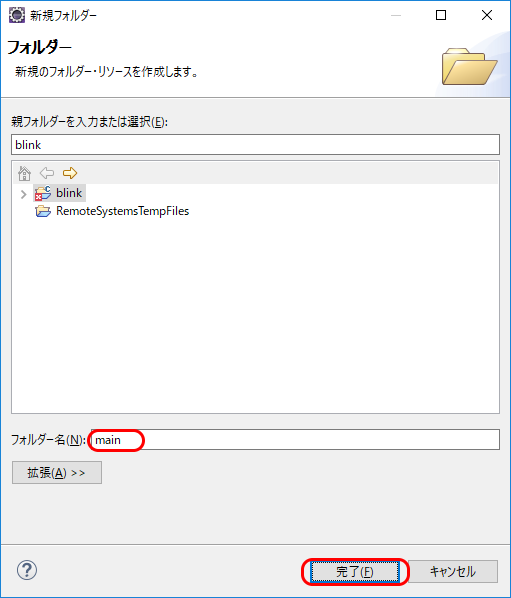
プロジェクト ルート を右クリックして[新規]-[フォルダー]を選択します。
-
[フォルダー名]に
mainを入力します。
-
[完了]ボタンを押します。
-
プロジェクト ルート を右クリックして[新規]-[フォルダー]を選択します。
-
プロジェクトの
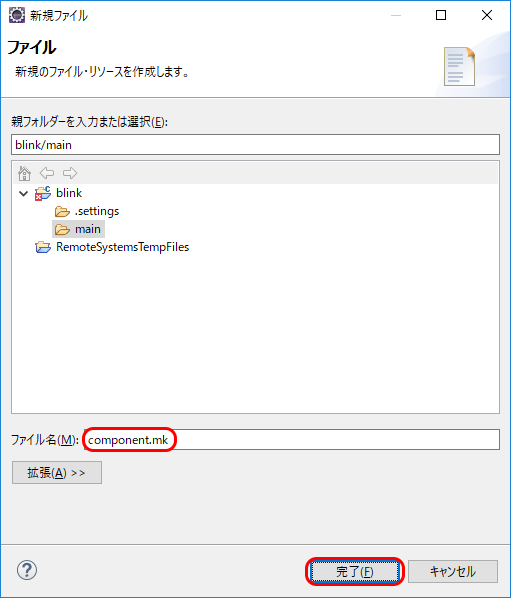
mainフォルダにcomponent.mkファイルを作成します。
-
mainフォルダを右クリックして[新規]-[ファイル]を選択します。

-
[ファイル名]に
component.mkを入力します。
-
[完了]ボタンを押します。
-
エディタで、次の内容を入力します。
#
# "main" pseudo-component makefile.
#
# (Uses default behaviour of compiling all source files in directory, adding 'include' to include path.)
-
-
プロジェクトの
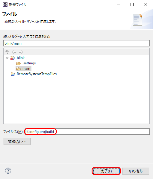
mainフォルダにKconfig.projbuildファイルを作成します。
-
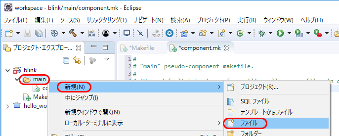
mainフォルダを右クリックして[新規]-[ファイル]を選択します。
-
[ファイル名]に
Kconfig.projbuildを入力します。
-
[完了]ボタンを押します。
-
エディタで、次の内容を入力します。
menu "Example Configuration"

config BLINK_GPIO
    int "Blink GPIO number"
	range 0 34
	default 5
	help
		GPIO number (IOxx) to blink on and off.

		Some GPIOs are used for other purposes (flash connections, etc.) and cannot be used to blink.

		GPIOs 35-39 are input-only so cannot be used as outputs.

endmenu
-
-
プロジェクトの
mainフォルダにblink.cファイルを作成します。
-
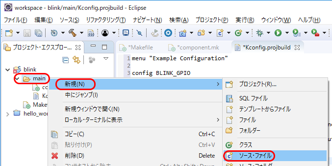
mainフォルダを右クリックして[新規]-[ソース・ファイル]を選択します。
-
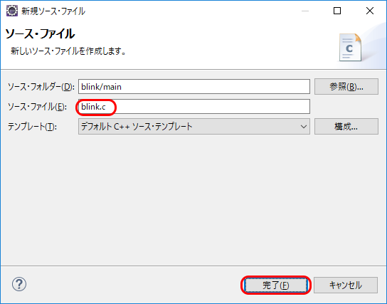
[ファイル名]に
blink.cを入力します。
-
[完了]ボタンを押します。
-
エディタで、次の内容を入力します。
/* Blink Example

   This example code is in the Public Domain (or CC0 licensed, at your option.)

   Unless required by applicable law or agreed to in writing, this
   software is distributed on an "AS IS" BASIS, WITHOUT WARRANTIES OR
   CONDITIONS OF ANY KIND, either express or implied.
*/
#include <stdio.h>
#include "freertos/FreeRTOS.h"
#include "freertos/task.h"
#include "driver/gpio.h"
#include "sdkconfig.h"

/* Can run 'make menuconfig' to choose the GPIO to blink,
   or you can edit the following line and set a number here.
*/
#define BLINK_GPIO CONFIG_BLINK_GPIO

void blink_task(void *pvParameter)
{
    /* Configure the IOMUX register for pad BLINK_GPIO (some pads are
       muxed to GPIO on reset already, but some default to other
       functions and need to be switched to GPIO. Consult the
       Technical Reference for a list of pads and their default
       functions.)
    */
    gpio_pad_select_gpio(BLINK_GPIO);
    /* Set the GPIO as a push/pull output */
    gpio_set_direction(BLINK_GPIO, GPIO_MODE_OUTPUT);
    while(1) {
        /* Blink off (output low) */
        gpio_set_level(BLINK_GPIO, 0);
        vTaskDelay(1000 / portTICK_PERIOD_MS);
        /* Blink on (output high) */
        gpio_set_level(BLINK_GPIO, 1);
        vTaskDelay(1000 / portTICK_PERIOD_MS);
    }
}

void app_main()
{
    xTaskCreate(&blink_task, "blink_task", configMINIMAL_STACK_SIZE, NULL, 5, NULL);
}
-
-
セーブします。
-
ツールバーの[すべて保存]ボタンを押します。

-
ツールバーの[すべて保存]ボタンを押します。
-
mingw32.exeを起動します。
-
カレントディレクトリをプロジェクト ルートに移動します。
$ cd /e/MyDocuments/Project/esp32/blink/ ↵
-
make menuconfigを実行します。
$ make menuconfig ↵
-
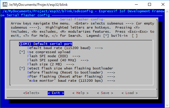
シリアルポートを設定します。
-
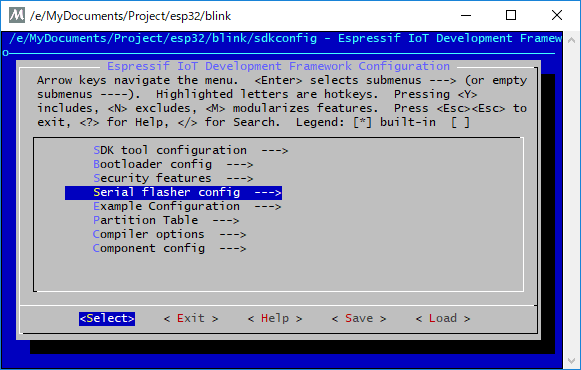
↑↓キーで[Serial flasher config]を選択します。
-
←→キーで[Select]を選択してEnterキーを押します。
-
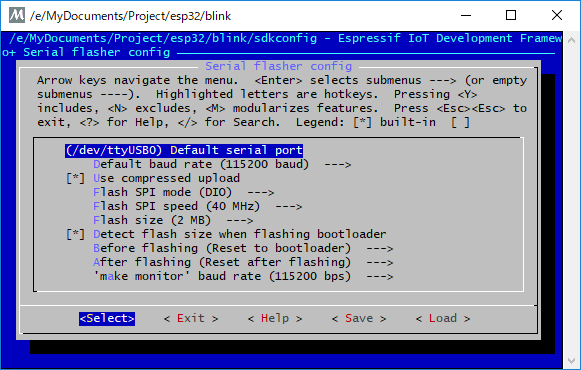
↑↓キーで[Default serial port]を選択します。
-
←→キーで[Select]を選択してEnterキーを押します。
-
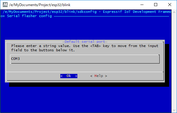
ポート名を入力します。
-
←→キーで[Ok]を選択してEnterキーを押します。
-
←→キーで[Exit]を選択してEnterキーを押します。
-
↑↓キーで[Serial flasher config]を選択します。
-
LEDを制御するGPIOポートを設定します。
Kconfig.projbuildで指定している値を変更できます。
-
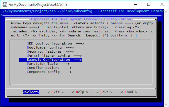
↑↓キーで[Example Configuration]を選択します。
-
←→キーで[Select]を選択してEnterキーを押します。
-
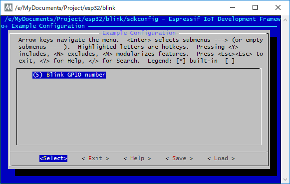
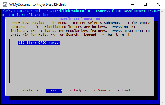
↑↓キーで[Blink GPIO number]を選択します。
-
←→キーで[Select]を選択してEnterキーを押します。
-
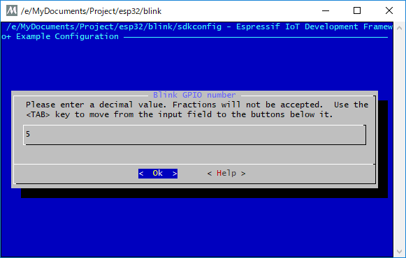
LEDの制御に使用するGPIOのポート番号を入力します。
-
←→キーで[Ok]を選択してEnterキーを押します。
-
←→キーで[Exit]を選択してEnterキーを押します。
-
↑↓キーで[Example Configuration]を選択します。
-
シリアルポートに出力するLogのレベルを変更します。
この設定はオプションです。
-
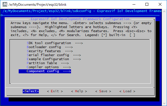
↑↓キーで[Component config]を選択します。
-
←→キーで[Select]を選択してEnterキーを押します。
-
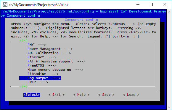
↑↓キーで[Log output]を選択します。
-
←→キーで[Select]を選択してEnterキーを押します。
-
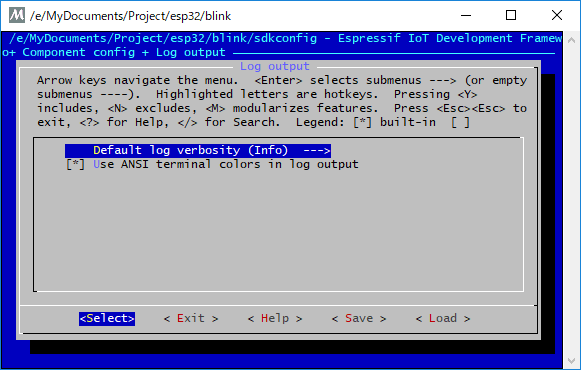
↑↓キーで[Default log vervosity]を選択します。
-
←→キーで[Select]を選択してEnterキーを押します。
-
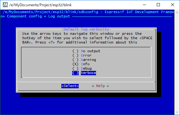
↑↓キーで出力するログのレベルを選択します。
-
←→キーで[Select]を選択してEnterキーを押します。
-
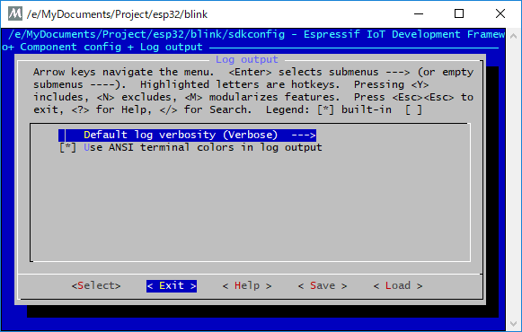
←→キーで[Exit]を選択してEnterキーを押します。
-
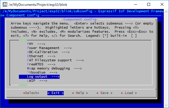
←→キーで[Exit]を選択してEnterキーを押します。
-
↑↓キーで[Component config]を選択します。
-
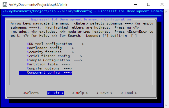
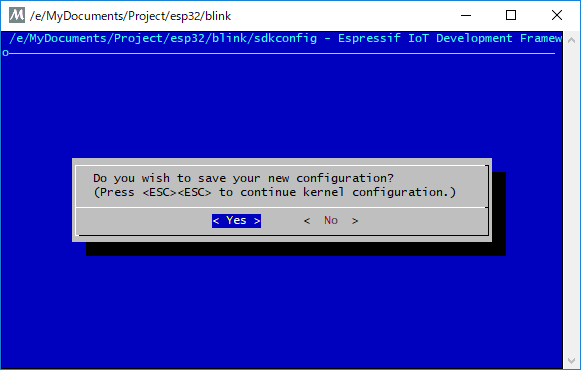
menuconfigを終了します。
-
←→キーで[Exit]を選択してEnterキーを押します。
-
←→キーで[Yes]を選択してEnterキーを押します。
-
←→キーで[Exit]を選択してEnterキーを押します。
-
Eclipseでクリーンしてビルド、そして
ビルド flashします。
動かしてみます
動作確認ができました。
Tweet